Spline support frame of roof
Create - shape - spline - line

Convert to editable poly - extrude length of building

Symmetry modifier to create roof

Architectual photos show two different images of the roof from orphograpic angles
The roof from the church side sows a singnificant slant being in the roof whereas the opposing ophographic view shows non
This has been compared with sattelite image of the roof and decided to process disregarding the slant until shown otherwise

Created chimney basics - used roof and chimney to re-align all four views
Bitmaps required altering which may lead to file merging problems
These shouldn't be significant on reflection

Create roof tiles section - cap end section if necessary
Add to roof layer

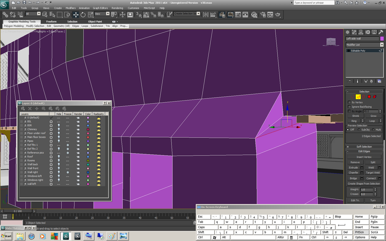
Decided to re-configure drivers to help with modeling - back face of geometry is no longer see through - to correct this go to object properties and select backface cull and switch on - geometry will no longer be able to be selected from back face - this can be seen as an advantage or a disadvantage depending on personal preference


Chimney - made see through - added 6 segments in height - editable poly - select edge - loop - move to position to effectiviliy cut chimney into segments

Extrude segments to match chimney profile

Same techniques created main body basic shape

Create geometry for all top floor window one side (use loop to control geometry on both sides)

Move single side of geometry to align geometry with windows on other side of building

Geometry will become ever more complicated - decided at this stage to seperate all four walls + roof section into seperate geometry to make visulisation easier

Create geometry for bottom windows

quicksliced to seperate geometry for indentation

Select polygons and indent to align with profiles

Using extrude is best option to not distort any other placed geometry - however will require excess created geometry to be removed

Remove windows and doorways geometry

Repeat for opposite side

Highlight geometry to be extruded

Extrude outwards as group

First attempt was incorrect - geometry was missed extruding geometry elected from side profile

Canceled extrude and highlighted underside geometry which was missed

Extrude - as group - geometry is forced in downwards direction to accommodate using local normal however this can be easily adjusted after extrude

Upper geometry is not required
Target weld to geometry below (select single vertex target weld to vertex below, move along to adjacent and target weld to vertex below it)

Repeat with next row to create desired result

Target weld corners to fix unnecessary geometry
Discovered (noticed) that holes left for windows connect directly onto side of new extruding geometry

This problem is on both sides

Capped window holes to replace previously removed geometry
Capped window geometry of windows directly above as well
Select horizontal edge where lower window previously resided
select ring - connect - add geometry line to separate window frames from newly extruded geometry
Repeat for opposite side

Return to orthographic view - see through to realign windows and extruded geometry

Highlight + remove window geometry again

No comments:
Post a Comment